AIO(All in Boom[爆炸就是艺术])现在很流行ESXI或者PVE, 我不太喜欢索性直接用Rocky Linux做宿主, 使用SSH + Cockpit Web控制台管理, 安装Rocky Linux很简单这里就不再赘述.

网卡直通这个一点不奇怪,不过大多数是用vfio-pci的ids来设置PCI设备的唯一标识符, 但是有个问题, 如果是多张卡或者多口卡那么就会全部被替代, 另外插PCIe插槽要注意, 只有PCH通道才能全部拆分IOMMU组, 如果是CPU通道, 那么大概率会跟多个设备一起被编在同一个IOMMU组.

使用命令行脚本查看IOMMU的组别情况, 如果我们要直通的设备并不是独立组, 那就无法直通了.

# for d in /sys/kernel/iommu_groups/*/devices/*; do n=${d#*/iommu_groups/*}; n=${n%%/*}; printf 'IOMMU Group %s ' "$n"; lspci -nns "${d##*/}"; done;
IOMMU Group 1 00:01.0 PCI bridge [0604]: Intel Corporation 6th-10th Gen Core Processor PCIe Controller (x16) [8086:1901] (rev 07)
IOMMU Group 1 00:01.1 PCI bridge [0604]: Intel Corporation Xeon E3-1200 v5/E3-1500 v5/6th Gen Core Processor PCIe Controller (x8) [8086:1905] (rev 07)
IOMMU Group 1 01:00.0 VGA compatible controller [0300]: NVIDIA Corporation GP108 [GeForce GT 1030] [10de:1d01] (rev a1)
IOMMU Group 1 01:00.1 Audio device [0403]: NVIDIA Corporation GP108 High Definition Audio Controller [10de:0fb8] (rev a1)
IOMMU Group 1 02:00.0 Ethernet controller [0200]: Intel Corporation 82580 Gigabit Network Connection [8086:150e] (rev 01)
IOMMU Group 1 02:00.1 Ethernet controller [0200]: Intel Corporation 82580 Gigabit Network Connection [8086:150e] (rev 01)
IOMMU Group 1 02:00.2 Ethernet controller [0200]: Intel Corporation 82580 Gigabit Network Connection [8086:150e] (rev 01)
IOMMU Group 1 02:00.3 Ethernet controller [0200]: Intel Corporation 82580 Gigabit Network Connection [8086:150e] (rev 01)

这个是插在CPU通道的情况,可以看到四口Intel 82580千兆网卡是在同一个IOMMU组, 这样就无法进行直通的, 我们在看一下插在PCH通道上的X710-DA4万兆网卡.

# for d in /sys/kernel/iommu_groups/*/devices/*; do n=${d#*/iommu_groups/*}; n=${n%%/*}; printf 'IOMMU Group %s ' "$n"; lspci -nns "${d##*/}"; done;
IOMMU Group 0 00:00.0 Host bridge [0600]: Intel Corporation Xeon E3-1200 v5/E3-1500 v5/6th Gen Core Processor Host Bridge/DRAM Registers [8086:1918] (rev 07)
...
IOMMU Group 20 0a:00.0 Ethernet controller [0200]: Intel Corporation Ethernet Controller X710 for 10GbE SFP+ [8086:1572] (rev 02)
IOMMU Group 21 0a:00.1 Ethernet controller [0200]: Intel Corporation Ethernet Controller X710 for 10GbE SFP+ [8086:1572] (rev 02)
IOMMU Group 22 0a:00.2 Ethernet controller [0200]: Intel Corporation Ethernet Controller X710 for 10GbE SFP+ [8086:1572] (rev 02)
IOMMU Group 23 0a:00.3 Ethernet controller [0200]: Intel Corporation Ethernet Controller X710 for 10GbE SFP+ [8086:1572] (rev 02)

这里可以看到0a:00.0、0a:00.1、0a:00.2、0a:00.3分别是X710-DA4的D、C、B、A, 是的PCI插槽序号正好跟光口的顺序相反, 他们的IOMMU组已经是独立的编号, 这样就可以分别直通, 记下需要直通的ID,我们这里是C、B、A三口, 即0000:0a:00.1 0000:0a:00.2 0000:0a:00.3。

建立启动脚本的dracut配置

# mkdir -p /usr/lib/dracut/modules.d/99vfio-pci
# touch /usr/lib/dracut/modules.d/99vfio-pci/module-setup.sh
# chmod +x /usr/lib/dracut/modules.d/99vfio-pci/module-setup.sh

# vi /usr/lib/dracut/modules.d/99vfio-pci/module-setup.sh

将dracut的配置代码输入进去.

#!/bin/bash
check() {
    if [ -d "/sys/module/vfio_pci" ]; then
        return 0
    else
        return 1
    fi
}
 
depends() {
    return 0
}
 
install() {
    inst_hook initqueue/start 05 
    declare moddir = \${moddir}
    inst_hook pre-udev 00 "\${moddir}/vfio-pci-init-script.sh"
}

编辑自动启动脚本

# vi /usr/lib/dracut/modules.d/99vfio-pci/vfio-pci-init-script.sh
#!/bin/sh
DEVS="0000:0a:00.1 0000:0a:00.2 0000:0a:00.3"
for DEV in $DEVS; do
    echo "vfio-pci" > /sys/bus/pci/devices/$DEV/driver_override
    echo $DEV > /sys/bus/pci/drivers/vfio-pci/bind
done
modprobe -i vfio-pci

这里的DEVS填写我们需要直通的PCI插槽序号, 即之前查看IOMMU组看到的序号.

; 设置可执行
# chmod +x /usr/lib/dracut/modules.d/99vfio-pci/vfio-pci-init-script.sh
; 重新生成Linux初始内存文件系统(initramfs)
# dracut /boot/initramfs-$(uname -r).img $(uname -r) --force

重启后查看vfio_pci设备信息, 可以看到驱动已经加载成功.

# ls /sys/bus/pci/drivers/vfio-pci -l
总用量 0
lrwxrwxrwx. 1 root root    0  3月  7 22:09 0000:0a:00.1 -> ../../../../devices/pci0000:00/0000:00:1d.0/0000:0a:00.1
lrwxrwxrwx. 1 root root    0  3月  7 22:09 0000:0a:00.2 -> ../../../../devices/pci0000:00/0000:00:1d.0/0000:0a:00.2
lrwxrwxrwx. 1 root root    0  3月  7 22:09 0000:0a:00.3 -> ../../../../devices/pci0000:00/0000:00:1d.0/0000:0a:00.3
--w-------. 1 root root 4096  3月  4 23:01 bind
lrwxrwxrwx. 1 root root    0  3月  7 22:09 module -> ../../../../module/vfio_pci
--w-------. 1 root root 4096  3月  7 22:09 new_id
--w-------. 1 root root 4096  3月  7 22:09 remove_id
--w-------. 1 root root 4096  3月  7 22:09 uevent
--w-------. 1 root root 4096  3月  7 22:09 unbind

获取需要直通PCIe设备的详细信息.

# virsh nodedev-list --tree |grep pci
...
  +- pci_0000_00_1d_0
  |   +- pci_0000_0a_00_0
  |   +- pci_0000_0a_00_1
  |   +- pci_0000_0a_00_2
  |   +- pci_0000_0a_00_3
...

Dump出需要直通的设备信息, pci_0000_0a_00_3 和 pci_0000_0a_00_2, 即X710的A口和B口.

# virsh nodedev-dumpxml pci_0000_0a_00_3
<device>
  <name>pci_0000_0a_00_3</name>
  <path>/sys/devices/pci0000:00/0000:00:1d.0/0000:0a:00.3</path>
  <parent>pci_0000_00_1d_0</parent>
  <driver>
    <name>vfio-pci</name>
  </driver>
  <capability type='pci'>
    <class>0x020000</class>
    <domain>0</domain>
    <bus>10</bus>
    <slot>0</slot>
    <function>3</function>
    <product id='0x1572'>Ethernet Controller X710 for 10GbE SFP+</product>
    <vendor id='0x8086'>Intel Corporation</vendor>
    <capability type='virt_functions' maxCount='32'/>
    <iommuGroup number='23'>
      <address domain='0x0000' bus='0x0a' slot='0x00' function='0x3'/>
    </iommuGroup>
    <pci-express>
      <link validity='cap' port='0' speed='8' width='4'/>
      <link validity='sta' speed='8' width='4'/>
    </pci-express>
  </capability>
</device>

# virsh nodedev-dumpxml pci_0000_0a_00_2
<device>
  <name>pci_0000_0a_00_2</name>
  <path>/sys/devices/pci0000:00/0000:00:1d.0/0000:0a:00.2</path>
  <parent>pci_0000_00_1d_0</parent>
  <driver>
    <name>vfio-pci</name>
  </driver>
  <capability type='pci'>
    <class>0x020000</class>
    <domain>0</domain>
    <bus>10</bus>
    <slot>0</slot>
    <function>2</function>
    <product id='0x1572'>Ethernet Controller X710 for 10GbE SFP+</product>
    <vendor id='0x8086'>Intel Corporation</vendor>
    <capability type='virt_functions' maxCount='32'/>
    <iommuGroup number='22'>
      <address domain='0x0000' bus='0x0a' slot='0x00' function='0x2'/>
    </iommuGroup>
    <pci-express>
      <link validity='cap' port='0' speed='8' width='4'/>
      <link validity='sta' speed='8' width='4'/>
    </pci-express>
  </capability>
</device>
; 下载OpenWrt x86 ext4固件
# wget https://downloads.openwrt.org/releases/24.10.0/targets/x86/64/openwrt-24.10.0-x86-64-generic-ext4-combined.img.gz
; 解压缩
# gzip -d openwrt-24.10.0-x86-64-generic-ext4-combined.img.gz

gzip: openwrt-24.10.0-x86-64-generic-ext4-combined.img.gz: decompression OK, trailing garbage ignored

; 将img镜像转换成qcow2硬盘镜像
# qemu-img convert -p -f raw -O qcow2 openwrt-24.10.0-x86-64-generic-ext4-combined.img openwrt-24.10.0-x86-64-generic-ext4-combined.qcow2

; 修改容量到20G
# qemu-img resize openwrt-24.10.0-x86-64-generic-ext4-combined.qcow2 20G
; 填充扩展容量到真实大小
# qemu-img resize -f raw openwrt-24.10.0-x86-64-generic-ext4-combined.qcow2 20G

编写XML openwrt.xml 来定义一台新的虚拟机.

# vi openwrt.xml
<domain type='kvm'>
    <name>openwrt_default_gateway</name>
    <memory unit='MiB'>2048</memory>
    <currentMemory unit='MiB'>2048</currentMemory>
    <vcpu>2</vcpu>
    <os>
        <type arch='x86_64' machine='pc-i440fx-8.2'>hvm</type>
        <boot dev='hd'/>
    </os>
    <features>
        <acpi/>
        <apic/>
    </features>
    <clock offset='utc'/>
    <on_poweroff>destroy</on_poweroff>
    <on_reboot>restart</on_reboot>
    <on_crash>destroy</on_crash>
    <devices>
        <emulator>/usr/bin/qemu-system-x86_64</emulator>
        <disk type='file' device='disk'>
            <driver name='qemu' type='qcow2'/>
            <source file='/data/libvirt/disk/openwrt-24.10.0-x86-64-generic-ext4-combined.qcow2'/>
            <target dev='vda' bus='virtio'/>
        </disk>
        <hostdev mode='subsystem' type='pci' managed='yes'>
            <driver name='vfio'/>
            <source>
                <address domain='0x0000' bus='0x0a' slot='0x00' function='0x3'/>
            </source>
        </hostdev>
        <hostdev mode='subsystem' type='pci' managed='yes'>
            <driver name='vfio'/>
            <source>
                <address domain='0x0000' bus='0x0a' slot='0x00' function='0x2'/>
            </source>
        </hostdev>
        <interface type='network'>
            <source network='v10gswitch'/>
            <model type='virtio'/>
        </interface>
        <controller type='usb' index='0'>
            <address type='pci' domain='0x0000' bus='0x00' solt='0x02' function='0x0'/>
        </controller>
        <input type='mouse' bus='ps2'/>
        <controller type='ide' index='0'>
            <address type='pci' domain='0x0000' bus='0x00' solt='0x01' function='0x0'/>
        </controller>
        <graphics type='vnc' port='-1' autoport='yes' listen='0.0.0.0'>
            <listen type='address' address='0.0.0.0'/>
        </graphics>
    </devices>
</domain>

创建虚拟机

# virsh define openwrt.xml

由于X710的驱动i40e在OpenWrt默认是没有的, 需要手动下载并拷贝进虚拟机, 否则因为没网络而无法继续.

# wget https://downloads.openwrt.org/releases/24.10.0/targets/x86/64/kmods/6.6.73-1-a21259e4f338051d27a6443a3a7f7f1f/kmod-i40e_6.6.73-r1_x86_64.ipk

拷贝 i40e 驱动到虚拟机中

# virt-copy-in -d openwrt_default_gateway kmod-i40e_6.6.73-r1_x86_64.ipk /root
; 如果提示 bash: virt-copy-in:未找到命令 则安装软件包.
# dnf install -y libguestfs-tools
; 如果提示 libguestfs: error: stat: /usr/libexec/qemu-kvm: 没有那个文件或目录 则做一下软连接.
# ln -s $(which qemu-kvm) /usr/libexec/qemu-kvm

在虚拟机中运行

# opkg kmod-i40e_6.6.73-r1_x86_64.ipk

在虚拟机中运行自动扩容脚本, OpenWrt官网有详细介绍, 见 https://openwrt.org/docs/guide-user/advanced/expand_root

# 直接配置自动扩容脚本
cat << "EOF" > /etc/uci-defaults/70-rootpt-resize
if [ ! -e /etc/rootpt-resize ] \
&& type parted > /dev/null \
&& lock -n /var/lock/root-resize
then
ROOT_BLK="$(readlink -f /sys/dev/block/"$(awk -e \
'$9=="/dev/root"{print $3}' /proc/self/mountinfo)")"
ROOT_DISK="/dev/$(basename "${ROOT_BLK%/*}")"
ROOT_PART="${ROOT_BLK##*[^0-9]}"
parted -f -s "${ROOT_DISK}" \
resizepart "${ROOT_PART}" 100%
mount_root done
touch /etc/rootpt-resize
reboot
fi
exit 1
EOF
cat << "EOF" > /etc/uci-defaults/80-rootfs-resize
if [ ! -e /etc/rootfs-resize ] \
&& [ -e /etc/rootpt-resize ] \
&& type losetup > /dev/null \
&& type resize2fs > /dev/null \
&& lock -n /var/lock/root-resize
then
ROOT_BLK="$(readlink -f /sys/dev/block/"$(awk -e \
'$9=="/dev/root"{print $3}' /proc/self/mountinfo)")"
ROOT_DEV="/dev/${ROOT_BLK##*/}"
LOOP_DEV="$(awk -e '$5=="/overlay"{print $9}' \
/proc/self/mountinfo)"
if [ -z "${LOOP_DEV}" ]
then
LOOP_DEV="$(losetup -f)"
losetup "${LOOP_DEV}" "${ROOT_DEV}"
fi
resize2fs -f "${LOOP_DEV}"
mount_root done
touch /etc/rootfs-resize
reboot
fi
exit 1
EOF
cat << "EOF" >> /etc/sysupgrade.conf
/etc/uci-defaults/70-rootpt-resize
/etc/uci-defaults/80-rootfs-resize
EOF
; 或者用wget获取自动扩容脚本
# wget -U "" -O expand-root.sh "https://openwrt.org/_export/code/docs/guide-user/advanced/expand_root?codeblock=0"
; 执行扩容脚本
# . ./expand-root.sh
; 安装需要的软件包
# opkg update
# opkg install parted losetup resize2fs
; 开始进行扩容, 这时候会自动重启, 等待扩容完毕即可.
# sh /etc/uci-defaults/70-rootpt-resize

至此OpenWrt已经创建完毕, 剩下就是更新源、安装简体中文语言支持以及安装需要的功能了.

# opkg update
# opkg install luci-i18n-base-zh-cn install luci-i18n-package-manager-zh-cn

; WOL网卡唤醒APP
# opkg install luci-i18n-wol-zh-cn

; 络流量监视器,它使用内核提供的网络接口统计信息
# opkg install luci-i18n-vnstat2-zh-cn

; 通用即插即用UPnP(端口自动转发)
# opkg install luci-i18n-upnp-zh-cn

; BT下载工具
# opkg install luci-i18n-transmission-zh-cn

; 流量监控工具
# opkg install luci-i18n-statistics-zh-cn

; 网络共享(Samba4)
# opkg install luci-i18n-samba4-zh-cn

; MWAN3负载均衡
# opkg install luci-i18n-mwan3-zh-cn

; 网页文件管理器
# opkg install luci-i18n-filebrowser-zh-cn

; 动态域名 DNS
# opkg install luci-i18n-ddns-zh-cn

; Aria2下载工具
# opkg install luci-i18n-aria2-zh-cn

; BanIP
# opkg install luci-i18n-banip-zh-cn

最后秀一把深水宝的双模光模块。

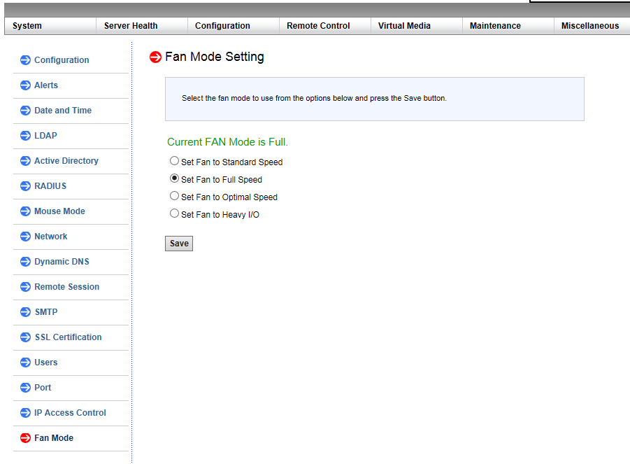
想要通过IPMI自定义风扇转速, 首先需要设置成Full模式, 进入IPMI设置界面, 在 Configuration 菜单下的 Fan Mode 设置成 Full 模式.

X9DR3-F的配置风扇风扇转速设置指令

; fan1-6的PWM设置指令, 设置范围是0到255, 这里的 0x6f 是 111 即 43.5%.
# ipmitool raw 0x30 0x91 0x5A 0x3 0x10 0x6f

; fana-b的PWM设置指令, 设置范围是0到255, 这里的 0x9f 是 159 即 62.3%.
# ipmitool raw 0x30 0x91 0x5A 0x3 0x11 0x9f

X11SSH-LN4F的配置风扇风扇转速设置指令

; fan1-4的PWM设置指令, 设置范围是0到100, 这里的 0x3c 即 60%.
# ipmitool raw 0x30 0x70 0x66 0x01 0x00 0x3c

; fana的PWM设置指令, 设置范围是0到100, 这里的 0x3c 即 60%.
# ipmitool raw 0x30 0x70 0x66 0x01 0x01 0x3c

以上就是IPMI直接设置风扇的调速指令, 现在建立一个服务使其开机自动设置.

$ sudo vi /etc/systemd/system/adjust-fanpwm.service
[Unit]
Description=Power on automatically adjusts fan PWM Service
After=network.target
 
[Service]
Type=simple
# fan1-6
# ipmitool raw 0x30 0x91 0x5A 0x3 0x10 0x6f
# fana-b
# ipmitool raw 0x30 0x91 0x5A 0x3 0x11 0x9f
ExecStart=/bin/bash -c 'sudo ipmitool raw 0x30 0x91 0x5A 0x3 0x10 0x6f && sudo ipmitool raw 0x30 0x91 0x5A 0x3 0x11 0x9f'
Restart=on-failure
 
[Install]
WantedBy=multi-user.target

设置成开机自动启动

$ sudo systemctl enable adjust-fanpwm.service

执行开机调节风扇PWM服务

$ sudo systemctl start adjust-fanpwm.service

查看执行情况

$ sudo systemctl status adjust-fanpwm.service

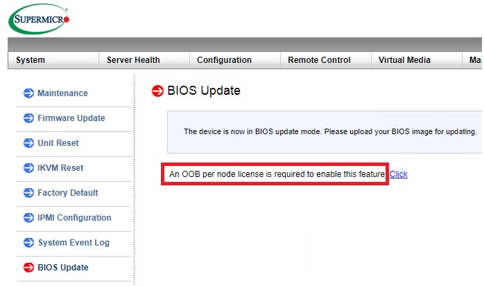
  最近入手一X11SCZ-F主板, 在其 Miscellaneous -> Activate License 需要输入 License ,搜索网上得知这个key在去年(2018年)被Peter Kleissner公开了生成算法twitter,用来方便用户更新BIOS。详细的文章在这里.

  就是使用MAC-SHA1-96 算法,对BMC的MAC码和 SECRET KEY: 85 44 E3 B4 7E CA 58 F9 58 30 43 F8 计算生成密码. MAC-SHA1-96表示利用MAC-SHA1计算,然后截取前96Bit。MAC- SHA1 的网站点这里.

  在linux下并安装了openssl, 可以直接计算:

echo -n 'bmc-mac' | xxd -r -p | openssl dgst -sha1 -mac HMAC -macopt hexkey:8544E3B47ECA58F9583043F8 | awk '{print $2}' | cut -c 1-24 

ps: bmc-mac 即IPMI BMC的MAC地址.

  详细文章如下: [来源: https://peterkleissner.com/2018/05/27/reverse-engineering-supermicro-ipmi/ ],来源网络 如有侵权 请联系删除.

Reverse Engineering Supermicro IPMI

May 27, 2018 | by Kleissner

Supermicro enforces a vendor-lock in on BIOS updates via IPMI, even though they publish the update files for free here. The only free alternative is to time-travel to 1995 and boot from a DOS disk to supply the update. All other options (including the Supermicro Server Manager) require a license.

They published BIOS updates to address Spectre and Meltdown vulnerabilities, yet make it almost impossible to actually perform the update. Even if you go their suggested way, buying a key from an authorized Supermicro reseller people on the internet report it’s difficult and time consuming getting them. I was quoted 25 EUR and an estimated 2 weeks delivery time.

You buy a brand new product, it has a known vulnerability and you should pay for the update?! This is simply NOT acceptable. As the owner of my device I shall be free to update it. Therefore, I spent exactly 1 night reverse engineering this thing to figure out the license key algorithm. tl;dr here is the algorithm to generate those license keys:

MAC-SHA1-96(INPUT: MAC address of BMC, SECRET KEY: 85 44 E3 B4 7E CA 58 F9 58 30 43 F8)

Anybody can create the license key on https://cryptii.com/ by typing on the left side (select Bytes) the MAC address of the IPMI (the BMC), select in the middle HMAC and SHA-1, enter the secret key and on the right side the License Key will appear!

This was successfully tested with Supermicro mainboards from 2013-2018. It appears they have not changed the algorithm and use the same “secret”. The first 6 groups go in here:

Update 1/14/2019: The Twitter user @astraleureka posted this code perl code which is generating the license key:

#!/usr/bin/perl
use strict;
use Digest::HMAC_SHA1 'hmac_sha1';
my $key  = "\x85\x44\xe3\xb4\x7e\xca\x58\xf9\x58\x30\x43\xf8";
my $mac  = shift || die 'args: mac-addr (i.e. 00:25:90:cd:26:da)';
my $data = join '', map { chr hex $_ } split ':', $mac;
my $raw  = hmac_sha1($data, $key);
printf "%02lX%02lX-%02lX%02lX-%02lX%02lX-%02lX%02lX-%02lX%02lX-%02lX%02lX\n", (map { ord $_ } split '', $raw);

Update 3/27/2019: There is also Linux shell version that uses openssl:

echo -n 'bmc-mac' | xxd -r -p | openssl dgst -sha1 -mac HMAC -macopt hexkey:8544E3B47ECA58F9583043F8 | awk '{print $2}' | cut -c 1-24
Information about IPMI (skip this if you’re an expert)

The IPMI is a remote management mechanism of servers, embedded in a chip that is separated from the typical resources accessible by the operating system. It allows remote management of servers even when it’s turned off. It’s really useful when your server is not responding and you don’t to want or can’t physically go there to troubleshoot. You can even install an OS via IPMI, start the server & even go into the BIOS. Thanks to HTML5 Supermicro switched away from those old Java applets (anyone developing anything in Java should be banned to a far, far remote island; Java should die in a fire, it’s slow and has 9999 vulnerabilities and on top of that Oracle will go after you for trademark and patent troll reasons even though it’s open source).

References that helped

I want to point out previous research work which helped me a lot.

Step 1: Download & Extract the Firmware

Supermicro offers the IPMI update files for free on their website. You need to select your mainboard and download the IPMI update file. Among other files it will contain 1 large firmware blob, in this case “REDFISH_X10_366.bin”.

The tool binwalk will scan the binary and look for signatures of known formats:

HEXADECIMAL DESCRIPTION
--------------------------------------------------------------------
0x19300 CRC32 polynomial table, little endian
0x400000 CramFS filesystem, little endian, size: 14254080, version 2, sorted_dirs, CRC 0xF105D0D5, edition 0, 8088 blocks, 1086 files
0x1400000 uImage header, header size: 64 bytes, header CRC: 0x8290B85A, created: 2017-06-09 12:33:02, image size: 1537474 bytes, Data Address: 0x40008000, Entry Point: 0x40008000, AA328F72, OS: Linux, CPU: ARM, image type: OS Kernel Image, compression type: gzip, image name: "21400000"
0x1400040 gzip compressed data, maximum compression, has original file name: "linux.bin", from Unix, last modified: 2017-06-09 12:01:11
0x1700000 CramFS filesystem, little endian, size: 7507968, version 2, sorted_dirs, CRC 0x19806BFF, edition 0, 2973 blocks, 407 files

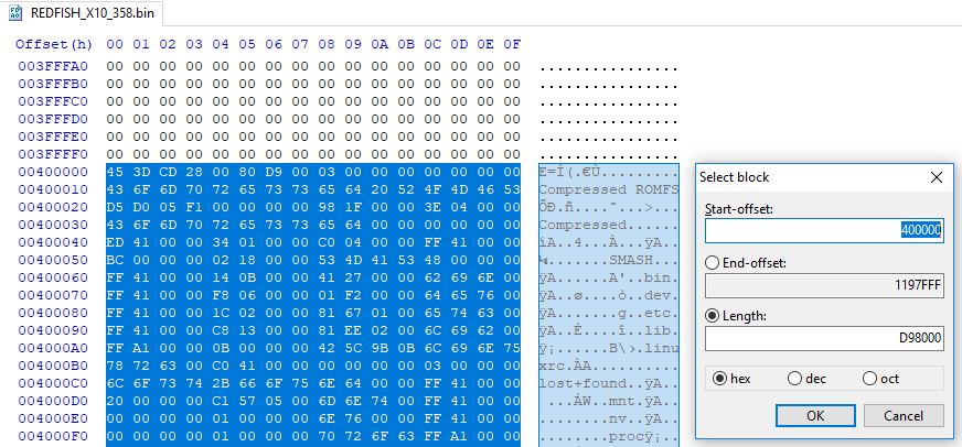
Use a hex editor (such as HxD) to extract the CramFS binaries and store them to new files. It is an embedded compressed Linux file system that contains the files that we are interested in.

Next get a Linux system and mount both files each with this command and then dump all files into a tar file:

mount -o loop -t cramfs extracted.bin mnt1
tar -czf mnt1.tar.gz mnt1

Congrats! You now have the actual files of the IPMI system.

Step 2: Reverse engineer the interesting files on the IPMI file system

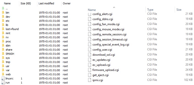
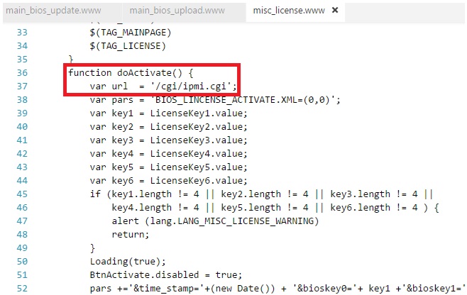
Finding the HTML/JS code that provides the user interface for activation was easy: Use the browser’s built-in developer tools (F12) to look at the code, then look for the same code on the extracted IPMI file system.

As you can see below, the IPMI website (that you visit as system administrator) calls “/cgi/ipmi.cgi” with certain parameters for checking if the key is valid.

Here are the breadcrumbs I followed from the website part:

The response is XML with check set to 0 if invalid and 1 if valid (it’s weird that they do not use JSON instead):

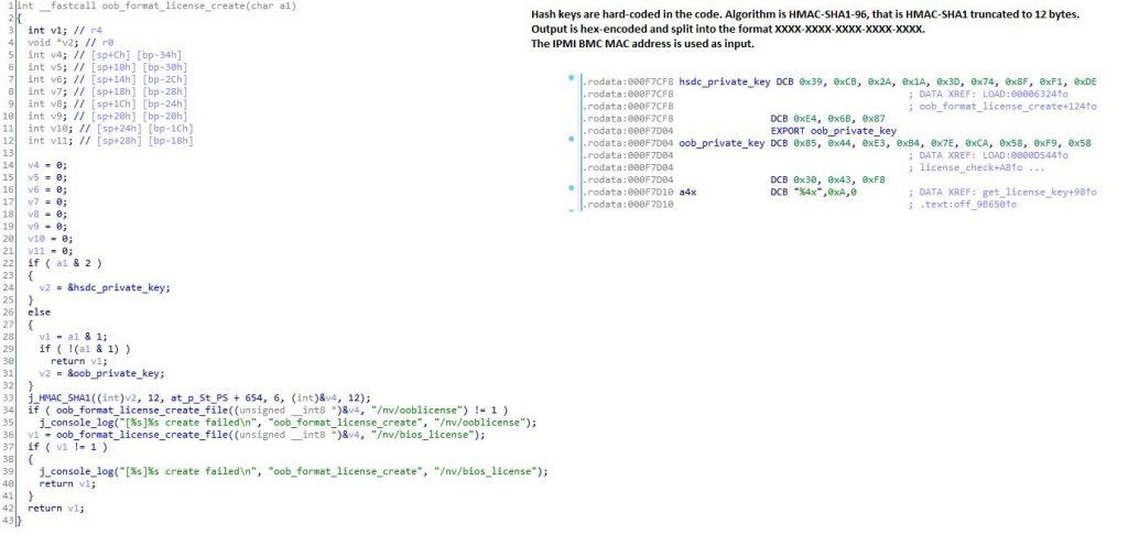
Next, we need to use IDA Pro and open the file “ipmi.cgi” that is stored on the IPMI file system and that we extracted in the previous step. Below you can see the code that handles the license check. By reading this code, you can see how the license is supposed to look like. The first loop is hex-decoding the input, i.e. The text key “1234-00FF-0000-0000-0000-0000” becomes binary (12 bytes) 12 34 00 FF 00 00 00 00 00 00 00 00.

The actual check of the license is done in another file “libipmi.so” which implements the referenced function oob_format_license_activate:

You can see here already the actual license key algorithm referenced – HMAC_SHA1. It is important to notice the 12 in the function call, which means 96 bits. The 96 bits is exactly the length of the key, represented in hex to the end-user.

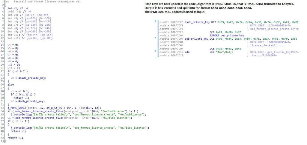
Interestingly there is a function “oob_format_license_create” which creates the license and is even easier to read. You can see directly the reference to the private keys. “oob” means out-of-band which is OEM talk meaning here remotely purchased license key (though there’s nothing remote about this function).

The Supermicro keys are:

HSDC Private Key: 39 CB 2A 1A 3D 74 8F F1 DE E4 6B 87

OOB Private Key: 85 44 E3 B4 7E CA 58 F9 58 30 43 F8

At the beginning of this blog post it is explained how you can easily use this to create your own Supermicro License Key.

1. 安装lm_sensors

$ sudo yum install lm_sensors

2. 配置探头信息

$ sudo sensors-detect

3. 在 /etc/sensors3.conf 中的配置传感器参数

$ sudo vi /etc/sensors3.conf
chip "it8782-*"

    label in0 "VCore"
    label in1 "+5V"
    label in2 "+12V"
    label in3 "+3.3V"
    label in4 "5VSB"
    label fan1 "SYS Fan 1"
    label fan2 "SYS Fan 2"

    ignore in7

    compute in0 ((3/10) +1)*@ ,   @/((3/10) +1)
    compute in1 ((6.8/10)+1)*@ ,  @/((6.8/10)+1)
    compute in2 ((30/10) +1)*@ ,  @/((30/10) +1)
    compute in4 ((6.8/10)+1)*@ ,  @/((6.8/10)+1)

    set in0_min 0.91
    set in0_max 1.21

    set in1_min 5 * 0.95 
    set in1_max 5 * 1.05

    set in2_min 12 * 0.95 
    set in2_max 12 * 1.05

    set in3_min 3.3 * 0.95 
    set in3_max 3.3 * 1.05

    set in4_min 5 * 0.95 
    set in4_max 5 * 1.05

    set fan1_min 0
    set fan2_min 0

4. 输出示例

it8782-isa-0a40
Adapter: ISA adapter
VCore: +1.04 V (min = +0.92 V, max = +1.21 V)
+5V: +5.05 V (min = +4.76 V, max = +5.24 V)
+12V: +11.90 V (min = +11.39 V, max = +12.61 V)
+3.3V: +3.33 V (min = +3.14 V, max = +3.47 V)
5VSB: +5.08 V (min = +4.76 V, max = +5.24 V)
Vbat: +3.22 V
SYS Fan 1: 0 RPM (min = 0 RPM)
SYS Fan 2: 0 RPM (min = 0 RPM)
temp1: +36.0°C (low = +8.0°C, high = -64.0°C) ALARM sensor = thermal diode
temp2: +36.0°C (low = +20.0°C, high = +0.0°C) ALARM sensor = thermal diode
intrusion0: ALARM

I. 安装时启动黑屏的问题

1. 安装程序启动时按TAB键盘编辑启动命令行,尾处添加 rdblacklist=gma500_gfx 禁用gma500_gfx驱动.

II. 更新最新内核(3.10.0-327.36.3)后启动卡死问题

1. 修改 /etc/default/grub 默认启动参, 添加 initcall_blacklist=clocksource_done_booting 参数.

aaaaaa

2. 执行 grub2-mkconfig –output /boot/grub2/grub.cfg 重新生成 grub2 启动配置.

III. 启动黑屏问题

1. 把gma500_gfx列入黑名单

vi /etc/modprobe.d/blacklist.conf
blacklist gma500_gfx

2. 重编initramfs

dracut -f

IV.附加

sv3-26026

电源接线图示

说明书: SV3-26026 User Manual